Page last updated 14 August, 2007
Parts you need to carry out this conversion - special inlet manifold, inlet manifold gasket, 2x rocker cover gaskets, 3x Weber 40DCNF carb's, linkage kit, fuel connector pipe, main jets/emulsion tubes/air correction jets/34mm venturi's for carbs, vacuum pipe fitting for servo take-off, water pipe fitting for heater take-off, M8 threaded rod for studs (this was the thread used in this particular manifold by the manufacturer, taps for 1/4" NPTF thread to allow fitment of air/water fittings, 3x high performance air filters.
Also shown is a set of 3 gasket/repair kits for carbs - a must to save time later (carb's & carb parts are difficult to obtain & can take months to arrive).
Procedure to follow before assembling parts on car
As I have just carried out this conversion, I hope this article will help anyone who decides to do it - saving them the trouble of sourcing the right parts from various suppliers.


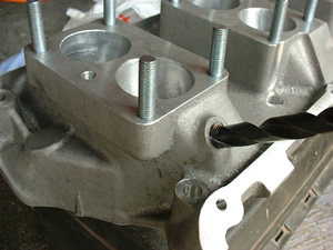
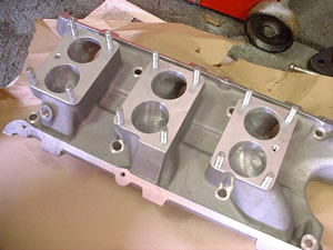
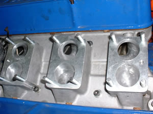
What you need to do is make sure the inlet manifold is free from casting flaws, and check that all the inlet ports are smooth from carb base through to head face. Once this has been checked, before getting the drill & grinding stones out, make the studs for the 3 carb bases. Each one needed to be 38mm in total length on the manifold I bought - although this may vary from item to item. You could have the studs longer on 3 of them, but the acceleration pump housing above one stud means this was the maximum height possible - allowing the fixing nut to be fully threaded once tightened. See pictures on the right for example.
Once you have 4 studs in a carb mount, place a gasket over these to check both ports on the manifold are no smaller than the gasket. Ideally the ports should be flush with the gasket, but it's not really a problem if they are slightly wider. The reason for this is to make best use of the inlet ports - smaller openings mean less air/fuel mixture will enter the engine, and a "step" in the flow of air caused by a smaller bore in the manifold will upset the airflow. Try to get each port identical to allow for the best possible match of airflow for each cylinder. Going back to the procedure, mark with a scribe or pencil the amount to be removed, then take off the gasket, unscrew the studs, and grind out exactly to you markings using a grinding attachment on a drill. The best type of drill to use for this type of work is an air drill (capable of very high rpm), with a carbide burr attachment (very hard material which will make light work of this job - especially as it's aluminium). An electric drill with a stone attachment will suffice if you have no access to the above, although running at a slower speed will take longer, and the stone attachments tend to clog up if you press too hard. As always, please ensure you wear good face & eye protection.
Next on the preparation is the air take-off for the brake servo, and the water take-off for the heater matrix. The manifold I used had a 1/8" NPTF threaded hole in no. 3 inlet port (for the servo fitting), an identical threaded hole at the back and front of the thermostat housing end of the manifold. One for the temperature sender (nearest no. 4 cylinder under the thermostat), and one for the heater pipe (near the distributor - also under the thermostat). I decided that the servo & heater pipe holes were too small because:
The fittings available for 1/8" NPTF allow a maximum internal diameter of 6mm for the pipe to attach to. The standard internal pipe bore for the servo is 3/8", and the heater pipe is 1/2" or 5/8". This internal pipe diameter of 6mm was around 4mm - probably OK for the servo, but was way too small to allow a generous flow of water to pass to the heater matrix - winter driving would have suffered (for those of you who drive your TVR in the winter....!)
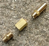
Now, 1/4" BSP fittings are similar to NPTF with the exception of the thread being slightly different. Don't let anyone tell you they are interchangeable because you don't want a leaking water or servo pipe, and once the thread is damaged you will be forced to go up to the next size fitting. NPTF thread is slightly deeper, and I suspect this is used for alloy parts as it ensures less chance of thread damage. BSP thread is more likely to strip if overtightened in such a soft metal. Lastly, the fittings are available in brass, mild steel, and stainless steel. I would opt to fit the brass or stainless items - but brass is safest if you want to protect the alloy thread.
What I decided to do was fit a 1/4" NPTF thread fitting for the servo take-off, with a pipe "tail" of 10mm diameter. This matched almost exactly the original Ford manifold's take-off - meaning the original pipe could be swapped over. The existing hole was drilled out & tapped with a 2nd stage tap (this allows a nice tight fit & longevity of thread if removal of fitting is to be done occasionally). See pictures on right for procedure.
I carried out the same operation for the heater hose take-off, but this time I was limited to the same maximum internal pipe diameter of the above servo pipe using the ¼" NPTF fittings. The problem was that the heater pipe has a 1/2" to 5/8" int. dia. pipe, so this fitting would be too small. NPTF fittings are limited, but BSP thread fittings are much more suitable, so to overcome this I purchased a male to male ¼" NPTF to ¼" BSPT fitting, a ¼" BSPP female to ¼" BSPP female fitting, then finally a ¼" BSPT male to ½" pipe tail fitting. Internal bore was ideal for the heater now - impossible using the fitting as per servo take-off which would screw directly into this hole. Although a long length of brass fittings compared to original, this was my only choice unless I went up to 3/8" NPTF fittings. This would be possible, but the inlet manifold would start to become thin around the hole & could possible crack if fitting too tight. I am still hunting for a ¼" NPTF male to ½" hose tail fitting - this would much improve the appearance of this area, and would be less likely to damage manifold if someone/something were to lean on the pipe! See picture further down for appearance of the final assembly.
Finally, the third hole above No.4 cylinder was already a suitable thread size to accept the standard Ford temperature sender unit - it simply screws in. A plan for the future is to fit a capillary water gauge as I feel they are more accurate - so for this I will fit an in-line adaptor tube which has a take-off for such a fitting. This will mean plugging the electric sender's hole - again with a 1/8" NPTF fitting. Just one point to note is that the temperature sender was originally located on the top of the manifold - not possible now due to front carburettor platform!
Final note on threads - BSPP means parallel thread, BSPT means tapered. Obviously a male tapered fitting goes into a female parallel fitting & vice versa.
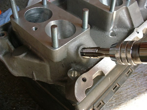


Do the same for the heater pipe take-off... Picture of this fitting later in section
Rolling road report - visit to Ric Wood on 1st October 2002
Once everything works & the engine runs, the only way to tune the engine for maximum efficiency & performance is to take it to a specialist with a rolling road. This is basically a set of rollers which allow the car to be "driven" while stationary, with the wheels allowed to spin as if on the road. This is important as the engine is under the correct loadings - simply revving the engine in neutral will not show up any fuel or ignition errors - they will only become apparent when driving. Also, there may be an unnoticeable error or poor setting which could cause engine damage - this will only show up on the rolling road.
Now, I tuned the engine to the best of my ability, but was still not happy with the performance, considering approx. 220bhp should be available now, compared with a standard V6 Essex producing 138bhp.
The car was booked in, and driven to Ric Wood's in Davenport (near Manchester) for early morning. After removing the bonnet to aid cooling (it has a quick release mechanism & wiring connector), Ric put the car on the rollers and placed a large fan against the radiator (as there is no airflow when stationary this powerful fan keeps the engine temperature down). The car was warmed up & driven through the gears, with various checks being made. Ric's expertise is second to none with these engines, and he immediately noticed a large reduction of power which he said was due to the cam timing being incorrect! Now, I spent a great deal of time when building this engine, but was not aware that the steel timing gears can have a manufacturing defect where the timing mark "dot" is one tooth out! It appeared that the engine was struggling to breathe correctly, and also explained the phenomenal fuel consumption on the journey up to Manchester (nearly 2 full tanks of fuel in 140 miles!). Due to this, and a faulty gauge, the car ran out of fuel on the rolling road, much to my embarrassment, so please make sure the tank is full when you go to a rolling road.
Ric said the first thing to do was to remove the front cover & re-set the cam timing. Luckily he was able to do this the same day, so I took a train to Manchester for the rest of the day - the station is literally at the end of the street so very convenient.
Upon my return, the cam timing had been done, and Ric now said that the performance had improved, but the exhaust & carbs needed further work to increase further. Basically, a standard TVR exhaust is fitted, and the two rear resonators are possible the cause of a large loss in power - due to not being straight through design. This is my first task as the power at the wheels is down approx. 30bhp from what it should be giving. Also, the carbs have 30mm inlet "ducts" built into them as can be seen on the photos, but these seriously affect the intake flow with my bespoke air filter - so they need to be cut down to flush with the air filter baseplate - allowing some special stub stacks to be fitted (Ric does cast alloy ones in two height sizes - essential to allow smooth airflow into carbs. Fuel jets & chokes were all recommended by Ric, so well in fact that no fuel adjustments had to be made except for at idle. He also set the standard distributor (now with no vacuum advance) to its optimal setting for maximum advance.
So, that's the story so far. The bhp is approx 120+ at the rear wheels, although full revs were not reached as the further work needs doing before a final power run. Ric reckoned it should be around 170, so the exhaust needs urgent attention. You may ask where the 220bhp comes from - well that's at the engine - you need to take off a some hp for gearbox & diff friction.
Driving home was amazing - the first time I've felt at ease driving the car. Power was awesome compared to the trip up, so make sure you set up the cam timing correctly. The engine sounds really good and just keeps pulling - the car now needs those uprated front brakes! Certainly it is a worthwhile mod. as the car is transformed into a real animal. Part throttle & deceleration now create a pop or six, which is something that will take some getting used to, but adds to the fun of driving. Needless to say this car won't be fitted with a stereo.....
For further updates, please see members section - as the mod's have continued since this artcle was published. To become a member, please see navigation bar at top of page. If you see no navigation bar, please click on the icon ![]()
Trial fitting - removal of existing inlet manifold & carburettor
Removal of the existing inlet manifold can be done with ease, once rocker covers have been removed (see roller rocker section for instructions). Then, follow the steps outlined below:


...which have to be filed down to allow correct position! This manifold is drilled & tapped for carbs/thermostat housing and main mounting studs, but you will need to check everything fits methodically as it is not a mass production item.